

DÜCHTING PUMPEN
DÜCHTING PUMPEN
DÜCHTING PUMPEN Co. is a private company. It was found by Wilhelm Düchting in the 1950s. Our motto "Quality through experience" forms the basis of our sophisticated range of products.
The capabilities of our company in the design, manufacture, testing and commissioning of our products is highly respected in the industries we serve. Our reputation is built on a sustainable corporate policy, efficiency, reliability, innovation and customer after-sales service.DÜCHTING PUMPEN Products:
Single-Stage Pumps:
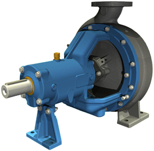
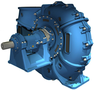
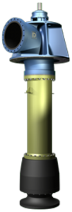
Type WR
- Pump Size: DN 32 to 800 mm
- Max. Pressure: 16 bar
- Max. Flow: 12,000 m3/h
- Total Head: 120 m
- Rotating Speed: to 3,600 rpm
- Field of Application: Pumping of abrasive and corrosive media.
- Material: from cast iron to SUPER DUPLEX stainless steel.
- Standards & Approvals: DIN / ASME
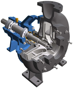
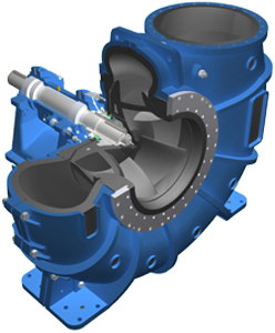
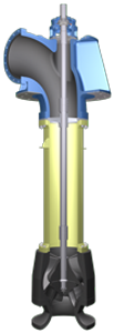
Type WRX
- Pump Size: DN 65 to 400 mm
- Max. Pressure: 10 bar
- Max. Flow: 4,000 m3/h
- Total Head: 90 m
- Rotating Speed: to 1,200 rpm
- Field of Application: Especially suitable for pumping highly abrasive and corrosive media with high to very high solid content.
- Material: from cast iron to SUPER DUPLEX stainless steel.
- Standards & Approvals: DIN / ASME
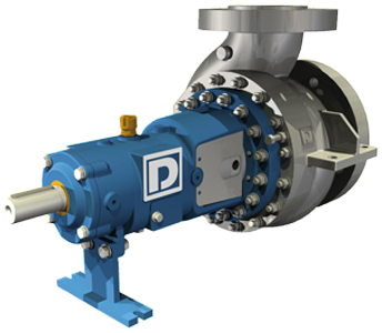
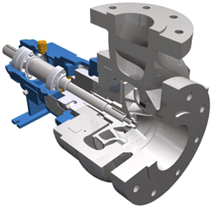
Type IP
- Pump Size: DN 50 to 450 mm
- Max. Pressure: 100 bar
- Max. Flow: 4,200 m3/h
- Total Head: 220 m
- Rotating Speed: to 3,600 rpm
- Field of Application: Suitable for handling of slightly abrasive and corrosive liquids.
- Material: from cast iron to SUPER DUPLEX stainless steel.
- Standards & Approvals: DIN / ASME / API 610 / ISO
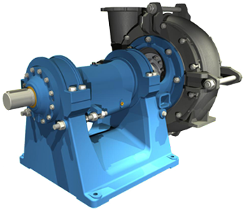
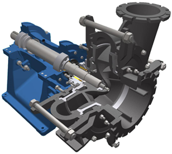
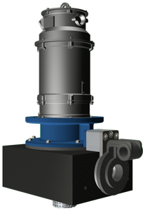
Type MC & MCS
- Pump Size: DN 32 to 300 mm
- Max. Pressure: 10 bar
- Max. Flow: 1,500 m3/h
- Total Head: 90 m
- Rotating Speed: to 3,600 rpm
- Field of Application: Pumping of abrasive and corrosive media.
- Material: SICcast®
- Standards & Approvals: DIN / ASME
Type MCC
- Pump Size: DN 400 to 1,000 mm
- Max. Pressure: 6 bar
- Max. Flow: 20,000 m3/h
- Total Head: 40 m
- Rotating Speed: to 1,200 rpm
- Field of Application: Pumping abrasive and / or corrosive media.
- Material: SICcast®
- Standards & Approvals: DIN / ASME
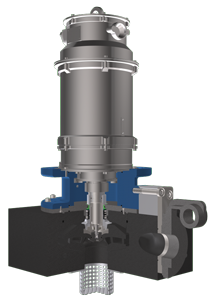
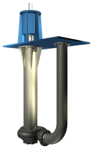
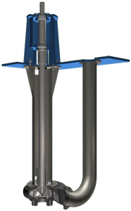
Type MCV
- Pump Size: DN 150 to 1,000 mm
- Max. Pressure: 8 bar
- Max. Flow: 12,500 m3/h
- Total Head: 60 m
- Rotating Speed: to 1,800 rpm
- Field of Application: Handling of abrasive and corrosive media.
- Material: SICcast®
- Standards & Approvals: DIN / ASME
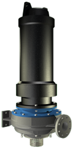
Type WRS
- Pump Size: DN 32 to 150 mm
- Max. Pressure: 10 bar
- Max. Flow: 370 m3/h
- Total Head: 90 m
- Rotating Speed: to 3,600 rpm
- Field of Application: Handling of abrasive and corrosive media.
- Material: DUPLEX stainless steel
- Standards & Approvals: DIN / ASME
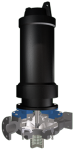
Type WRV
- Pump Size: DN 32 to 400 mm
- Max. Pressure: 16 bar
- Max. Flow: 4,000 m3/h
- Total Head: 120 m
- Rotating Speed: to 3,600 rpm
- Field of Application: Handling of abrasive and corrosive media.
- Material: DUPLEX stainless steel
- Standards & Approvals: DIN / ASME
Multi-Stage Pumps:
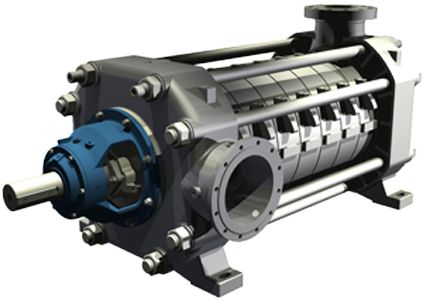
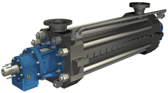
Type HPXU
- Pump Size: DN 32 to 400 mm
- Max. Pressure: 160 bar
- Max. Flow: 3,250 m3/h
- Total Head: 1,200 m
- Rotating Speed: to 3,600 rpm
- Field of Application: Handling of contaminated, chemically neutral or aggressive liquids with up to 10% solids.
- Material: from cast iron to SUPER DUPLEX stainless steel.
- Standards & Approvals: DIN / ASME / API 610 / ISO
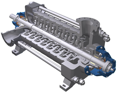
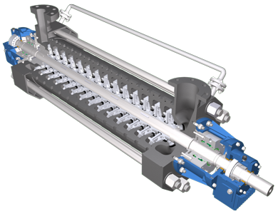
Type HPE
- Pump Size: DN 50 to 300 mm
- Max. Pressure: 250 bar
- Max. Flow: 3,500 m3/h
- Total Head: 2,200 m
- Rotating Speed: to 3,600 rpm
- Field of Application: Handling of clean or slightly polluted, chemically neutral or aggressive liquids.
- Material: from cast iron to SUPER DUPLEX stainless steel.
- Standards & Approvals: DIN / ASME / API 610 / ISO
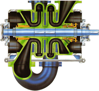
Type ROWA-2/4 S
- Pump Size: DN 100 to 300 mm
- Max. Pressure: 40 bar
- Max. Flow: 2,000 m3/h
- Total Head: 350 m
- Rotating Speed: to 1,800 rpm
- Field of Application: Handling of abrasive and corrosive media.
- Material: from cast iron to SUPER DUPLEX stainless steel.
- Standards & Approvals: DIN / ASME
SICcast® constructs, produces and coats parts subject to strong erosion corrosion, abrasion and/or corrosion in liquid media based on patented silicon carbide materials.
Silicon carbide (SiC) is the central part of our abrasion and corrosion resilient materials. Silicon carbide is an almost diamond-hard (Mohs scale 9.7), synthetically produced material that is industrially produced.For more information about SICcast®, please Contact Us or visit SICcast® website. Top ▲
For more information, please Contact Us or visit DÜCHTING website. Top ▲
MENZEL ELEKTROMOTOREN
MENZEL ELEKTROMOTOREN
MENZEL was founded in 1927 in Berlin, Germany. MENZEL is a medium-sized globally active company for drive technology with great experience in the production and delivery of electric motors for all types of industrial applications.
MENZEL Products:
MENZEL keeps more than 20,000 electric motors of all types, generators and transformers ready for you straight from the warehouse. Modifications and individual adaptations are possible within a short period of time.
- Low voltage motors of up to 2,500 kW
- High voltage motors of up to 20,000 kW
- Squirrel cage and slip ring motors
- Direct-current motors of up to 2,000 kW
- Transformers of all power ranges
- Frequency converters and frequency converter-proof drives
- Rotating frequency changer–even custom-built
For more information, please Contact Us or visit MENZEL website. Top ▲
PAPE & OLBERTZ
PAPE & OLBERTZ
Pape & Olbertz, foundation in Cologne-Germany in 1919, is one of the leading manufacturers of starters, resistors and switchgears for industry. Our innovative medium-sized enterprise offers customer-specific solutions as a basis of mutual success. Our function-oriented and low-maintenance products give customers high levels of reliability for the machines, thus assuring their long-term economic success.
PAPE & OLBERTZ Products:
Resistance Starters:
- Liquid Starters
- Oil Roller Starters
- Oil Contactor Starters
Soft Starters:
- Variable Frequency Drives (VFD)
- Variable Speed Drives (VSD)
Resistors:
- Starting Resistors
- Slip Resistors
- Braking Resistors
- Railway Resistors
- Crane Resistors
Tap Changers
Switchgears
SCADA System
For more information, please Contact Us or visit PAPE & OLBERTZ website. Top ▲
QUA-VAC
QUA-VAC
Vacuflow® Vacuum Sewage Technology:
History of Vacuum Sewage Technology:
In 1956, the Swedish engineer Joel Liljendahl filed a patent on vacuum collection and transport of toilet waste by means of air. In 1968, Electrolux A.B Sweden bought the rights on the vacuum technology as specified by the inventor Mr. Joel Liljendahl. In 1969, Electrolux- Quatfass B.V developed the Vacuflow system. In 1985, Electrolux- Quatfass B.V sold its total vacuum division to EVAC A.B Finland. In 1990, Mr. D.G. Quatfass Managing Director of QUA-VAC B.V Holland bought all worldwide Vacuflow rights from EVAC A.B.
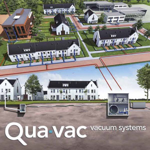
Vacuflow® gives value to the customers by low investments costs and excellent results. The Vacuflow® system is robust and simple. It consists of a collection chamber (where wastewater is collected), a pipe network (through which wastewater is transported) and a vacuum station (which maintains the vacuum throughout the entire system). Negative pressure in the Vacuflow® system is between 65-25 kPa (0.65-0.25 Bar). Wastewater transportation velocity in the Vacuflow® system reaches up to 6 m/sec.
How it works?
Wastewater enters the collection chamber and when it rises above a certain level the vacuum valve opens. Due to negative pressure wastewater is transported through the pipe network to the vacuum station. Because of high transport speeds the wastewater will only remain briefly within the pipe network.
Vacuflow® Vacuum Sewage Technology
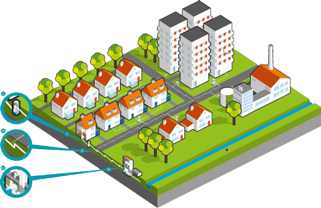
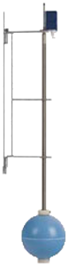
I. Collection chamber:
Houses are connected to a collection chamber where wastewater is collected. The collection chamber has a vacuum valve that is automatically activated when wastewater reaches a certain level.
Vacuflow collection chamber equipment
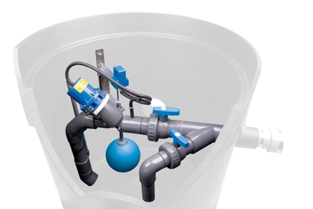
Vacuflow vacuum valve, level controller & Simultaneous Air and Water suction pipe
Advantage: the collection chambers operate pneumatically/mechanically which therefore do not require electricity.
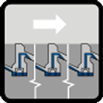
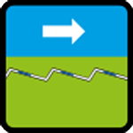
II. Pipe network:
The pipe network consists of PVC or HDPE pipes. A central vacuum station keeps this pipe network under negative pressure. Due to their small diameter, the pipes can be laid at depths of 80 to 120 centimeters under the ground surface. The addition of air makes the wastewater lighter, which leads to higher transport speeds. The pipe network is laid in a "saw tooth profile". Within this profile, a mixture of wastewater and air from the collection chamber is transported to the vacuum station.
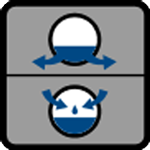
a. Wastewater at rest:
Within the pipeline network, the wastewater at rest flows into deeper lying "pockets".
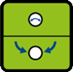
b. Activating the collection chamber:
Once the collection chamber in the pipeline network is activated, the mixture of wastewater and air is transported towards the vacuum station.
c. Deactivating the collection chamber:
Once the collection chamber is deactivated, the collection chamber, the entire system will come to rest. One transportation cycle has then been completed.
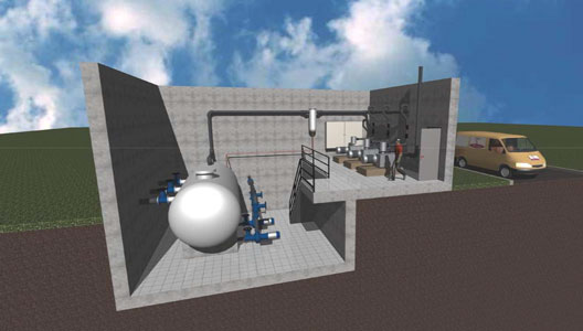
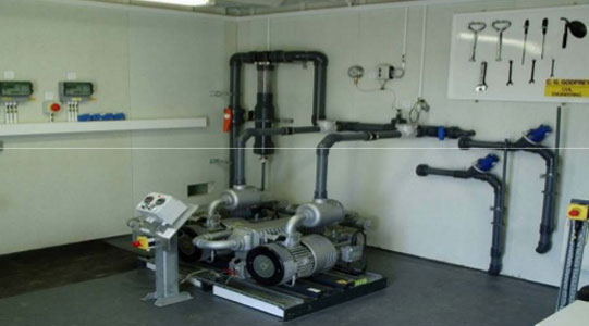
III. Vacuum pumps station:
The wastewater from the collection chamber is transported through the pipe network and enters in the vacuum tank (1). The vacuum in the tank is generated by vacuum pumps (2). The extracted air from the vacuum tank can be purified with a Bio-filter or active carbon filter, if necessary (3). The level in the tank is measured with an ultrasonic gauge. The pressure pump(s) will be activated at high level (4) and the wastewater will be transported to the sewage purification. The pressure pump(s) will stop automatically at low level.
Qua-Vac Vacuum pumps station
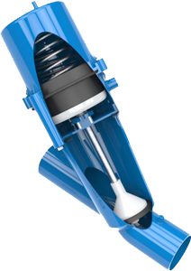
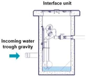
Operation of Vacuum Collection Chamber of Vacuflow® system:
1- Wastewater flows under gravity into the bufferpot. The Vacuflow® valve is closed in this situation.
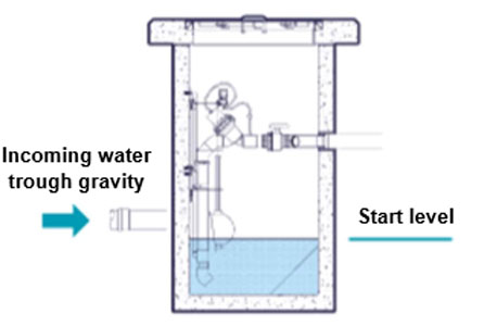
2- The starting level is reached and the Vacuflow® valve is opened by the starter valve on the float mechanism.
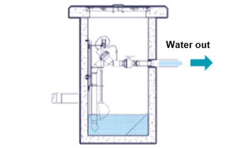
3- The wastewater collected as a water-air mixture is transported out of the bufferpot in the piping network.
4- The stop level is reached and the Vacuflow® valve is closed by turning off the starter valve. One transportation cycle has then been completed.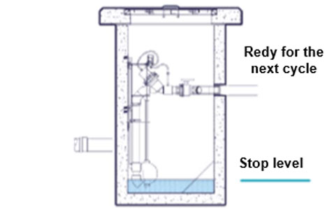
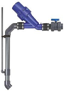
Vacuflow Collection Chamber:
Houses or buildings are connected to a Vacuflow Collection unit- a chamber where the wastewater is collected by gravity. The Vacuflow Collection chamber has a vacuum valve that is automatically activated when wastewater reaches a certain level.
The Vacuflow collection chamber has great advantages:
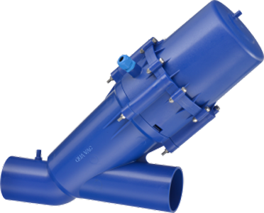
QUA-VAC has several different Vacuum valves sizes but most commonly used are the 63mm and 90mm for transport of sewage outside buildings.
- No electricity
- Batch volume of 30-120 liters
- Fully submersible valve and level controller
- Standard By-pass suction device (for emergency cases)
- No "breather pipe" needed
- Material of chamber PE/PP or Concrete
- Transport of air and water simultaneously
- Buffer capacity of the complete chamber
The advantages of the QUA-VAC system:
- Low investment costs
- Minimal maintenance
- Quick excavation
- Low energy consumption
- No ground pollution
- Small diameters
- No deep trenches
- Flexibility of piping
- Aeration of sewage
The system consists of:
One of the characteristic features of the Vacuflow® system is the presence of a bufferpot. This bufferpot is actually an extra security in the system. Should however a power failure occur, then this bufferpot will have a "reserve storage" capacity of approx. 24 hours. In general the Vacuflow® system is used especially when and if a lot of connections and a large flow capacity is required. A typical example is a project where 1500 houses use this system in a ribbon development alongside a canal. Totally 72 kilometers of vacuum piping and more than 1000 interface valve units are installed.
- House connection
- Interface bufferpot
- Automatic vacuum valve
- Vacuum pipeline
- Ejector or vacuum pump station
- Rising main
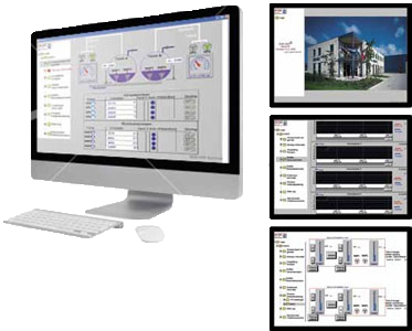
Qua-Vac’s Aquatell Telemetry & Scada system for monitoring and cycle counting:
The Aquatell software can contact the vacuum station by modem and import all station data. On this screen, the complete layout is shown with all vacuum mainlines and pots. Each pot has a unique code to indicate the location. Pot cycle counting is achieved by data logging, showing opening and closing times of all pots throughout the day.
Qua-Vac’s Aquatell Telemetry & Scada system
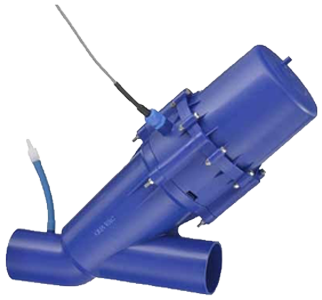
On site advanced interactive trouble shooting monitor:
For each individual vacuum network, a unique geographical plan is made for the electronic touch screen, showing pot location, behavior and eventual alarm.
Qua-Vac valve 90 mm with monitoring sensor
Advantages of vacuum sewer system VS Gravity sewer System
Gravity system
Vacuum system
Complex:
Numerous lift stations with their high capital cost and maintenance requirements are utilized to offset excessive excavation and trenching costs.
Simplicity:
Non-continuous slope allows shallow trenching to be used resulting in substantial excavation cost savings and reduced installation time.
Dewatering:
Excavating in areas of high water table is expensive due to complicated and time consuming dewatering and trench stabilization procedures.

No dewatering:
Small diameter mains, installed just below frost level allow shallow and narrow trenching thereby minimizing construction time and environmental disturbances.

Road obstructions:
Wide and deep trenches often make roads impossible to pedestrians and vehicular traffic for long periods of time. Damage to trees and landscaping can be severe.

No road obstructions:
Small diameter mains, installed just below frost level allow shallow and narrow trenching thereby minimizing construction time and environmental disturbances.

Pollution:
Exfiltration can contaminate the surrounding area (water source, lakes and rivers). Infiltration is a serious problem resulting in existing treatment becoming hydraulically overloaded and the imposition of compulsory over-sizing of treatment plants under design.
No pollution:
Absolutely fail - safe - field tested and operated under vacuum conditions. A broken main, at worst, results in infiltration (easily detected) - never exfiltration.
Non Flexible:
Unforeseen obstructions such as water or sewer mains, large rocks, etc. usually result in expensive field changes and line rerouting.

Flexible:
Vertical lift capability allows unforeseen obstructions to be easily passed over, under, or around resulting in minimum delay and eliminating extra costs.

High investment:
200 mm up to 400 mm diameter concrete pipe and vitrified clay pipe sewer main are typical with material costs and excessive unit labor costs.
Low investment:
90 mm up to 200mm diameter PVC or HDPE vacuum sewer mains are typical. Labor and materials costs for installing vacuum piping are dramatically lower, compared to gravity sewers, due to labor and trenching costs associated with smaller diameter vacuum main.
Qua-Vac features in a glance:
Worldwide, the Qua-Vac interface unit equipment has replaced whole networks equipped with inferior vacuum valves of various manufacturers.
- From 1969 installed in many worldwide systems
- Full submersible valve and level controller
- No "breather pipe" needed
- Absence of level sensing pipe
- Highly reliable pneumatic/mechanical level float device
- No grease built up
- Simultaneous Air and Water suction and transport
- Unique patented air/water venture suction device
- Guaranteed air/water ratio control in whole network
- Automatic air/water restore even after temporary system shut down
- No re-set or maintenance needed
- Standard By-pass suction device (for emergency cases)
- Standard Ball type of manual shut-off valves included
- All equipment in non-corrosion and chemical proof materials
- Easy dismantling of valve, suction pipe and float activator
- Optional: valve monitoring and cycle counting
For more information, please Contact Us or visit QUA-VAC website. Top ▲
VALORSABIO
VALORSABIO
VALORSABIO is a leading consulting and engineering firm for environmental and renewable energies, providing services in Environmental Engineering sectors, Research & Innovation, Technology Transfer, Intellectual Property & Know-How Management, Sustainability Consulting.
VALORSABIO Solutions Showcase:
- JET-LOOP SYSTEM, JET-LOOP PRO, TURBO-JET AERATION, ZEOREACTOR, ZEOPACK, ZEOFAST, MBR PLATE
SECONDARY WASTEWATER TREATMENT
- GREENLINE, ALGAE-CLEAN, MICRO-BARRIER
TERTIARY WASTEWATER TREATMENT
- CASPRO, CAS+, CWS, VOCLEAN, NOx-PLUS
GASES AND ODOR CONTROL
- AG-BAG, COMPOSTER
SLUDGE & SOLID WASTE TREATMENT AND DISPOSAL
- SYNERGY, BIO-SUN, MG-BAG
CARBON CAPTURE AND CDM PROGRAMS
- METHANER, UASB HYBRID, UASB-PRO©, THERMOPHIL, JET-MIX
BIOGAS & ANAEROBIC SYSTEMS
- PROECO, BIO-BARRIERS
ENVIRONMENTAL MANAGEMENT & HABITATS SUSTAINABILITY
- FERMATEC, MWG, BD-FLASH, BIFLUX, CONTIZYM, TRIVAC
RENEWABLE ENERGIES & BIOFUELS
JET-LOOP SYSTEM
The JET-LOOP SYSTEM was developed by Eng. Antonio Ferreira. The first conceptual designs were plot during 1997. The tests and prototype demonstration were performed during 1997, 98 and 1999.
JET-LOOP® UNIQUE ADVANTAGES:
The first commercial application was sold during 1999. The JET-LOOP SYSTEM is now installed in several countries, with applications municipal and industrial wastewater streams.
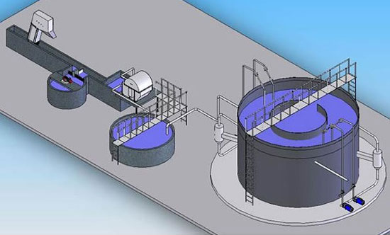
The Jet-Loop System©® applies for aerobic wastewater treatment using special designed ejector(s) as the mechanical system for aeration.
The ejector(s) are installed outside and above the effluent, and the air aspirated at the air inlet is conducted with the effluent in circulation to the bottom of the aeration bioreactor, by a draft tube.
The design and engineering of the ejector(s) and the aeration loop is unique, since it is able to introduce air against a depth of liquid not less than 7,5 m, and at the same time, keeps the volume of aspirated air and the consumption of energy between limits that turn the system the most efficient in oxygen transfer to the effluent and the one among all other processes that spent less energy in the aeration process.
The Jet-Loop System©® doesn't produce any significant amount of excess sludge (MLSS), since it combines together three innovative features:
1- The ejector was designed to perfection, for creating the maximum sudden chock pressure and shear stress to the activated sludge (MLVSS) passing in the ejector, thus damaging and effectively destroying excess biomass.
2- The age of the cells inside the Bioreactor were increased into a maximum, by recirculation of MLSS to the bioreactor from the filtration devices at the output of the process.
3- The loop created between the ejector and the bioreactor is made in a way that prevents the biomass in the lower parts of the bioreactor to be washed out.
In terms of energy consumption and due to the high global oxygen transfer coefficient, the system can operate to levels of electricity consumption, below 50% any existing process.
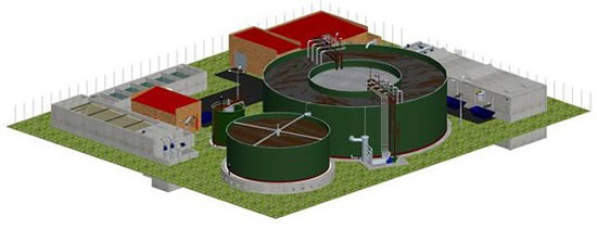
The Jet-Loop System©® is well adapted for the treatment of very high charged organic loads, as industrial biodegradable effluents, as well as less contaminated effluents, as in municipal wastewater treatment. It can be installed in any size from small communities, up to the biggest cities, depending only in the size of the bioreactor(s) all together with the number of ejectors to be installed and operated. The installation is fast and competitive, especially if it applies for the use of prefabricated steel bolted tanks for the bioreactors.
The operation of the system is very simple and reliable due to the innovative designed technology, and also without any special maintenance, since it is composed by no moving mechanical parts with the exception of the centrifugal pump(s) that driven the effluent throw the ejector(s).Other key advantages:
- Near Zero Sludge Production.
- Very Low Energy Consumption.
- Low volume and space installation.
- Competitive cost of installation.
- Mechanical reliability bolted steel tanks construction.
- No moving parts.
- Very low maintenance.
- Fast and easy installation.
- Easy operation.
Comparative Sludge Production
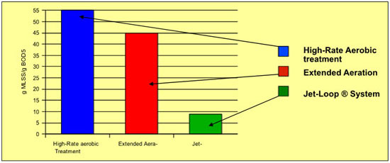
Example: wastewater treatment plant for 1M habitants city:
- High-Rate sludge production: 55gBOD5x1Mx0,55=30,250 Tons/day.
- Extended Aeration: = 24,750 Tons/day.
- JET-LOOP® SYSTEM: = 4,950 Tons/day.
Sludge difference per year: (30,250-4,950)x365= 9.234,5 Tons/year.Comparative Energy Consumption
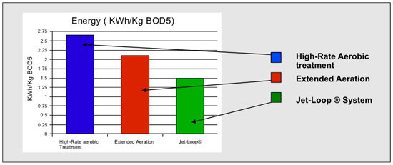
Example: wastewater treatment plant for 1M habitants city:
- High-Rate AEROBIC TREATMENT energy required: 5.958KWh.
- Extended Aeration: = 4.812 KWh.
- JET-LOOP®: = 1.895 kWh.
Energy difference per year: (5.958-3.437)x24x365= 35.591 Mw/year.
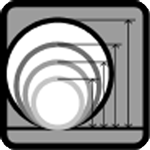
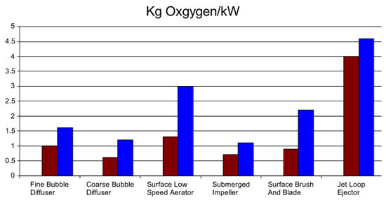
Typical Ranges of Oxygen Transfer Capabilities For Various Aerators
How does the Jet-Loop System aeration work?
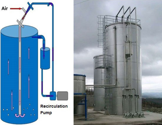
3D Perspective for Illustration of Jet-Loop System
13 Jet-Loop System WWTP 15.000 m3/day were performed by VALORSABIO in Baghdad- Iraq in 2008
For more information about JET-LOOP SYSTEM, please Contact Us or visit VALORSABIO website. Top ▲
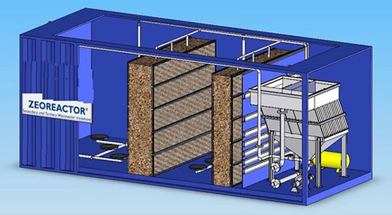
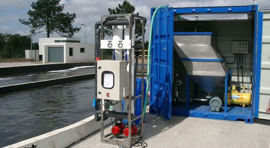
ZEOREACTOR
ZEOREACTOR ©® is new biological wastewater treatment process, using modules of immobilized zeolites.
ZEOREACTOR ©® Unique Characteristics:Application fields/sectors:
- Secondary and tertiary treatment in one stage.
- Nutrient removal (N).
- Improved BOD5 reduction.
- Domestic wastewater.
- Industrial wastewate.
ZEOREACTOR
For more information about ZEOREACTOR, please Contact Us or visit VALORSABIO website. Top ▲
GREENLINE
The GREENLINE is a photoreactor based on the author acronym LMMP (Linear Matrix Multicellular Photoreactor), now a widely used terminology among scientific community.
3D Perspective for Illustration of GREENLINE
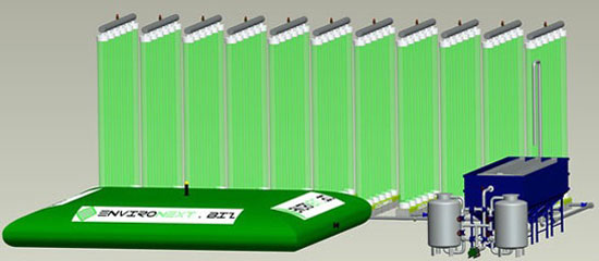
The actual process/ technology was under WIPO patent pending nº : WO2008010737A1, and the inventor is Antonio Manuel Cardoso Marques Ferreira, the actual owner and CEO of VALORSABIO, Lda.
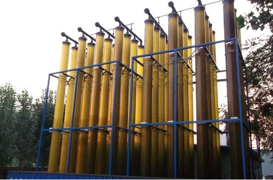
The GREENLINE is a solution to grow microalgae and uses for the case transparent and vertical tubes. The tubes are set in rows and interconnected by collectors at the ends (top and bottom collectors). The solution uses several rows in series in order to achieve: 1) the required efficiency for a specific microalgae growing and corresponding effect; 2) for collecting as must light as possible using the less possible optimized foot print.
The GREENLINE include also a feeding pump for raw wastewater feed and a centrifugal recirculation pump that returns the final treated wastewater with the microalgae culture, to the initial point of feeding. The objective for this recirculation action is to: 1) lower the inlet wastewater NTU (turbidity), and 2) allow for a more complete mixture / turbulence in the circulation wastewater. The system includes sensors for light detection, pH, temperature and Oxygen contents in the water.
The GREENLINE includes also a tank for mixing the return water with the raw wastewater and also a final pre-clarification tank for the microalgae recovery. On the top of the collectors, are installed valves for oxygen purge/ release as gas.
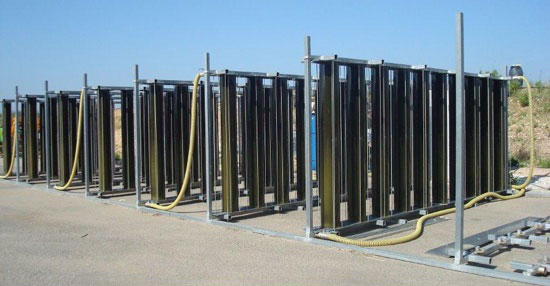
The transparent tubes in the demonstration solution were produces in PET (Poly Ethyl Terephthalate), the same grade PET used in water bottling. The PET proves to be a very good resistant plastic, able to resist both the UV long term exposition and to handle the changes in pH, from the collectors were made in stainless steel (SS AISI 304) and the gaskets / flanges that connect the tubes to the collectors were built in Butadiene Rubber.
The GREENLINE combines several very advanced parts:
A) The microbiological understanding related with the microalgae growing process is on the center of the innovation. The GREENLINE can grow microalgae, at a fast rate and great efficiency, using a combination of turbulent flow, vertical path and transient light/ shade. This unique process demonstrated that it is possible to lower the wastewater hydraulic retention time to a low level as only 3 hours, without compromising the treated water parameters.
B) The correct dimensioning for the specs and detailed engineering for the GREENLINE are now at our competence, as a result of the long term evolution and demonstration tests. From the materials used up to the kinetics, the process in now understood up to a level that is well above the competitors.
C) The use of recycled materials such as PET from water bottles and rubber from used tires, inscribes the GREENLINE in the sustainable and environmental friendly economy.
D) The configuration in vertical path demonstrates to be at once simple but unbeatable. Together with the low foot print involved, it becomes demonstrated that this innovative solution achieves the very best CO2 and organic loads handling capacities.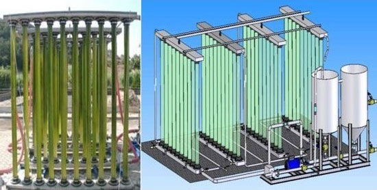
GREENLINE FIELDS OF APPLICATIONS:
- The solution can be applied for general Tertiary wastewater treatment, where Nitrogen and Phosphorous removal are essential.
- In addition to nutrients removal, the reducing and elimination of residual COD and BOD5 are in the capacities of the solution.
- The GREENLINE can also be applied for specific cases, such as heavy metals removal and recalcitrant chemicals removal.
- Several sectors are under the GREENLINE best application, such as the fish and shrimp ponds production, agro-industry wastewater treatment polishing, microalgae production, etc.
- The GREENLINE can be used for carbon dioxide sequestration and for microalgae production for biodiesel.
GREENLINE Results (Partial Secondary & Tertiary Wastewater treatment)
Inflow CQO in CBO5 in SST in N in P in 140 26 44 40 7,9 Outflow CQO out CBO5 out SST out N out P out 30 4 4,3 1,6 0,2
Note: All units in mg/L. Operational data obtained in continuous flow, with 3 hours hydraulic retention time.
GREENLINE vs. other Treatments (nitrogen removal)
Treatment operation or process Removal of total nitrogen entering process(%) Conventional treatment Primary 5-10 Secondary 10-30 Biological processes Bacterial assimilation 30-70 Denitrification 70-95 of nitrates Harvesting algae 50-80 Nitrification 5-20 Oxidation ponds 20-90 Chemical processes Breakpoint chlorination 80-95 of amonia and organic nitrogen Chemical coagulation 20-30 Carbon adsorption 10-20 Selective Ion exchange for ammonium 70-95 of ammonia Selective Ion exchange for nitrate 70-90 of nitrates Physical Operations Filtration 20-40 Air Stripping 50-90 of ammonia Electrodialysis 40-50 Reverse Osmosis 80-90 GREENLINE Up to 95
GREENLINE vs. other Treatments (phosphorous removal)
Treatment Phosphorous removal (%) Primary 10-20 Activated-sludge 10-25 Trickling-filter 8-12 Rotating biological contactors 8-12 Biological phosphorous removal only Mainstream treatment (A/O) 70-90 Sidestream treatment (PhoStrip) 70-90 Combined biological nitrogen and phosphorous removal 70-90 Chemical Removal Precipitation with metal salt 70-90 Precipitation with lime 70-90 Physical Removal Filtration 20-50 Reverse Osmosis 90-100 Carbon adsorption 10-30 GREENLINE Up to 97
GREENLINE vs. other Treatments (Desing and operation)
Typical design information for combined removal of nitrogen and phosphorous by biological processes
Parameter Process Unit A²/O B* UCT VIP G.L Retention time h 4,5-8,5 9,5-23 9-22 4,5-8 3-6 Solids Retention d 4-27 10-40 10-30 5-10 1-8 Oxygen Production No No No No Yes Needs air supply Yes Yes Yes Yes No Return activates sludge % influent 20-50 50-100 50-100 50-100 0-25 Chemicals Addition Yes Yes Yes Yes No
Bardenpho*For more information about GREENLINE, please Contact Us or visit VALORSABIO website. Top ▲
For more information about VALORSABIO Solutions Showcase, please Contact Us or visit VALORSABIO website. Top ▲